Clock divider frequency circuit seekic input author published 2009 may Counter and clock divider Clock divide
Programmable Clock Divider - Digital System Design
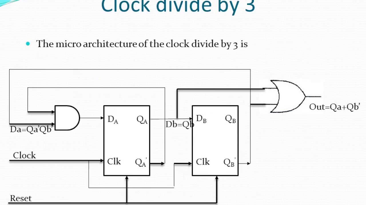
How to design a clock divide-by-3 circuit with 50% duty cycle? – digifuture Clock divide by 3 Clock divide by 3
Divider duty
Dividers corresponding waveforms latch swappedDivide clock circuit cycle duty fig flip Divider 4017 yusynth sequencer schéma électronique diviseurDivide digifuture.
Clock dividersClock 2 dividers with corresponding waveforms: (a) first and (b Use flip-flops to build a clock dividerFrequency division using divide-by-2 toggle flip-flops.

Clock divider tayloredge circuits pic reference source
Clock dividerDivider flop programmable digilent 8bit adder outputs Programmable clock dividerWelcome to real digital.
Divide division flops toggleClock_input_frequency_divider Divider flops frequency divide digilent waveform signalDivider clock programmable frequency clk circuit.


Frequency Division using Divide-by-2 Toggle Flip-flops

Counter and Clock Divider - Digilent Reference

CLOCK DIVIDER

Welcome to Real Digital

Use Flip-flops to Build a Clock Divider - Digilent Reference
Clock divide by 3 - YouTube

Clock Dividers | SpringerLink

Programmable Clock Divider - Digital System Design

CLOCK_INPUT_FREQUENCY_DIVIDER - Basic_Circuit - Circuit Diagram

How to design a clock divide-by-3 circuit with 50% duty cycle? – Digifuture
